I considered to build my own trailer but because of all red tape that sticks to a home built trailer for 80 km/h (50 mph) I went for a conversion.
This is how I converted a motorboat trailer to a TI trailer.
Se pictures below
The post has been edited. The texts are now above each related picture.
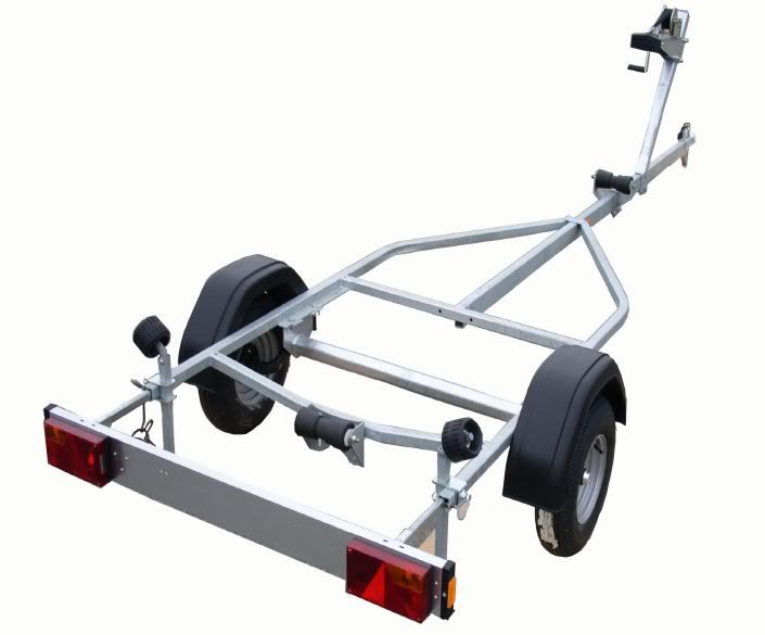
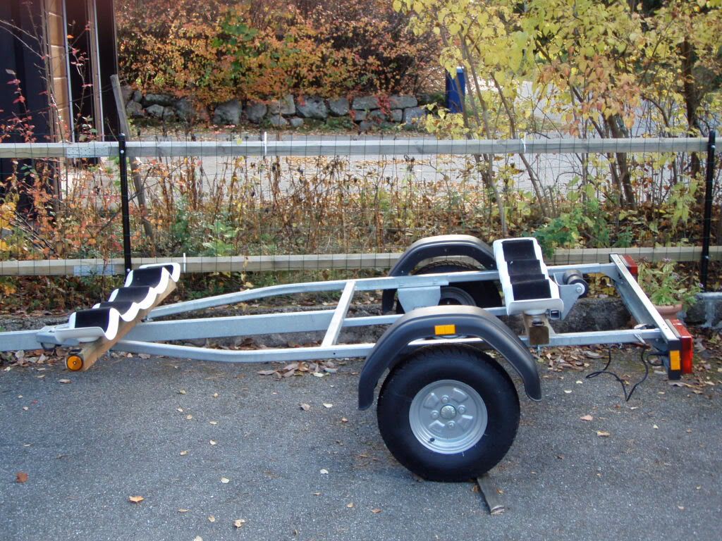
1. The trailer is an Easyline 450 (Corresponds to Thule 500) This type of trailer with no breaks is usually referred to as "Eurotrailer".
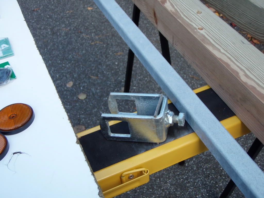
2. I detached winch tower and side support rollers. (On the picture the new bar is already fitted)
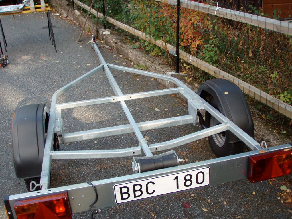
3. I saved one side support clamp for locking the new bar
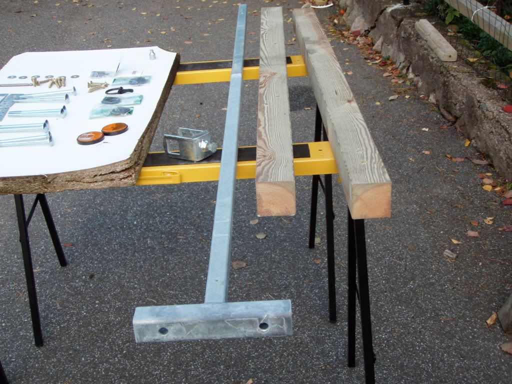
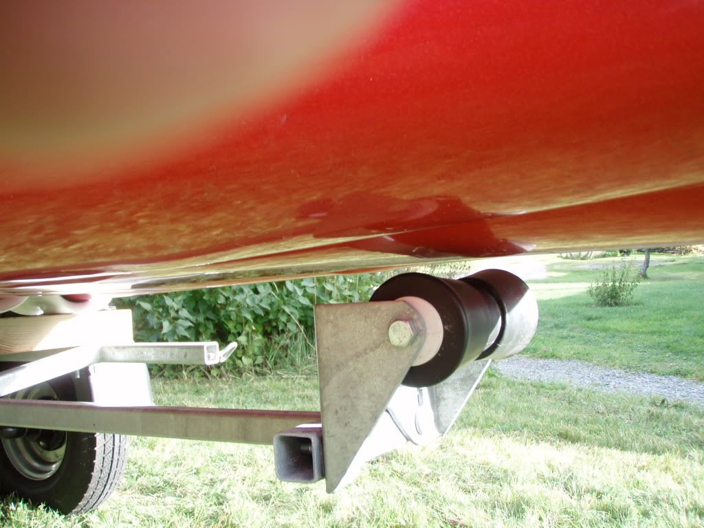
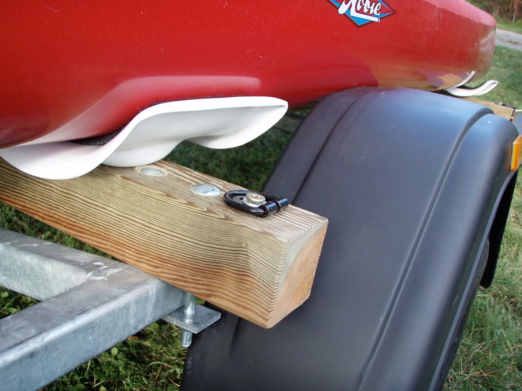
4. I had a new steel bar made for moving the aft keel roller further back. I had the new bar galvanized. The bar is 1920 mm long with a square section of 30 x 30 x 3 mm. The end part will be modified, se below. I made two beams of impregnated pine, which I treated with wood oil. The dimensions are 70 x 70 x 1360 mm. 70 mm was selected in order to get the amas high enough to clear the mudguards.
5. I fixed the beams with square necked bolts M10 (140 mm) and double pieces of 2.5 mm galvanized steel. I was fortunate to find standard pieces. The wood screws (8 x 50 mm) are for fitting the cradles to the wood beams and also the black D-rings for securing the boat. Screws are suitable for impregnated wood and uses T40 bits. I use washers under all screwheads.
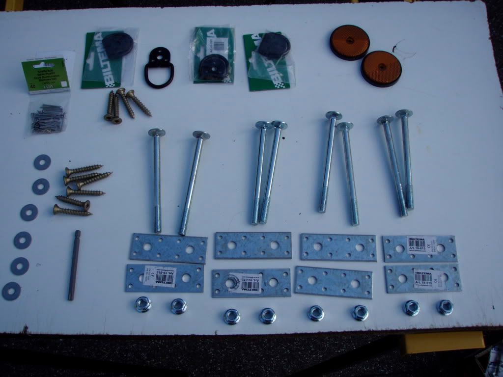
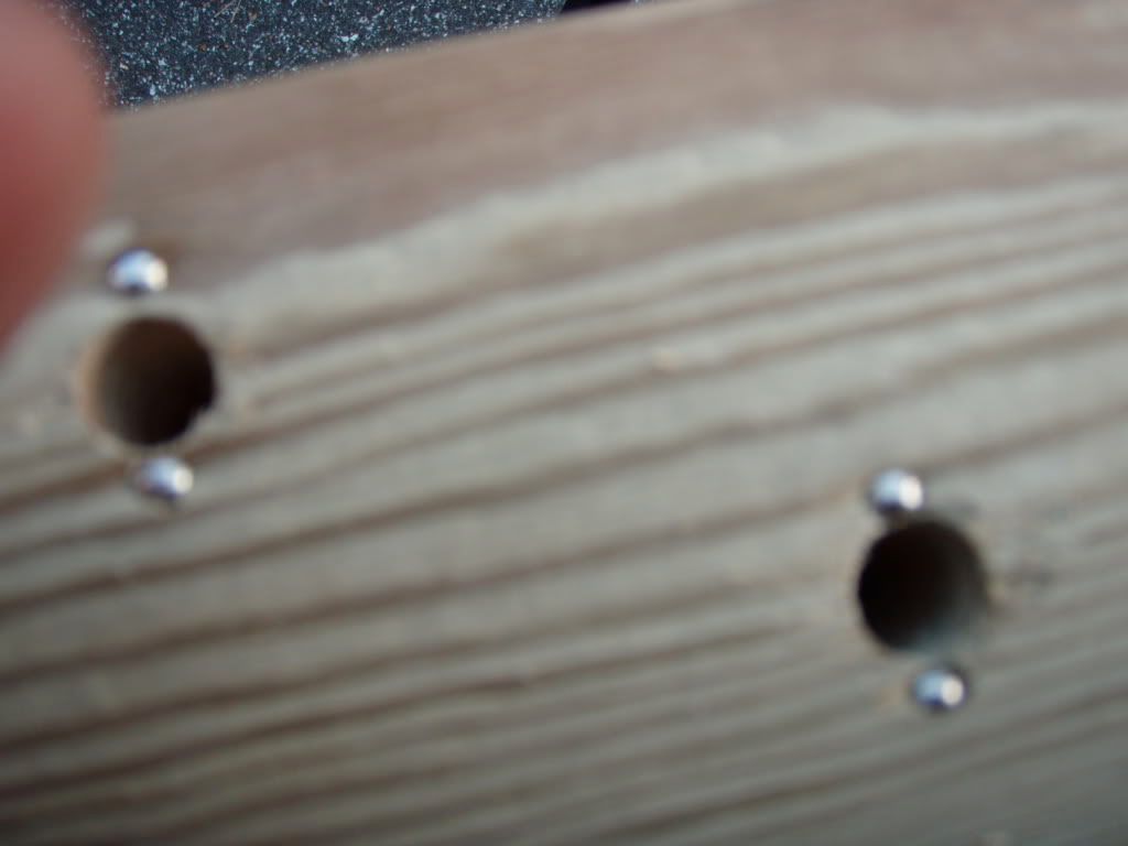
6. I reinforced the boltholes in the wood with stainless nails, as square necked bolts tend to rotate in soft wood. (I had to countersink a bit to make the bolts flush with the wood as the cradle hit the spot where the bolts are located. Hence I had to hit the nails further into the wood. Do not use nylock nuts with square necked bolts as they may make the bolts go round in the wood.
7. The new bar fits nicely into the pulling bar.
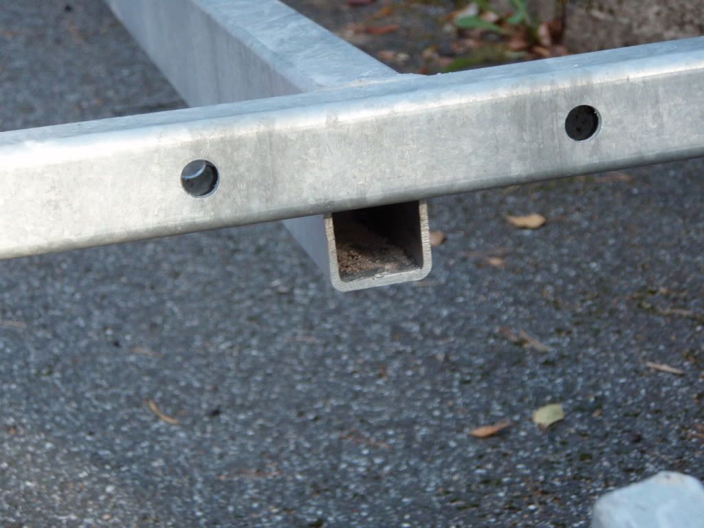
8. The bar can be pushed in. I limited the length in order not to hit the light cable that goes into the pulling beam at the Y-junction.
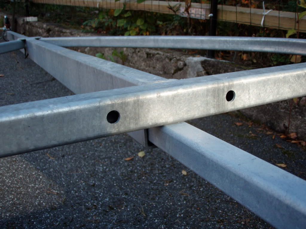
9. The new bar is locked by the existing clamp.

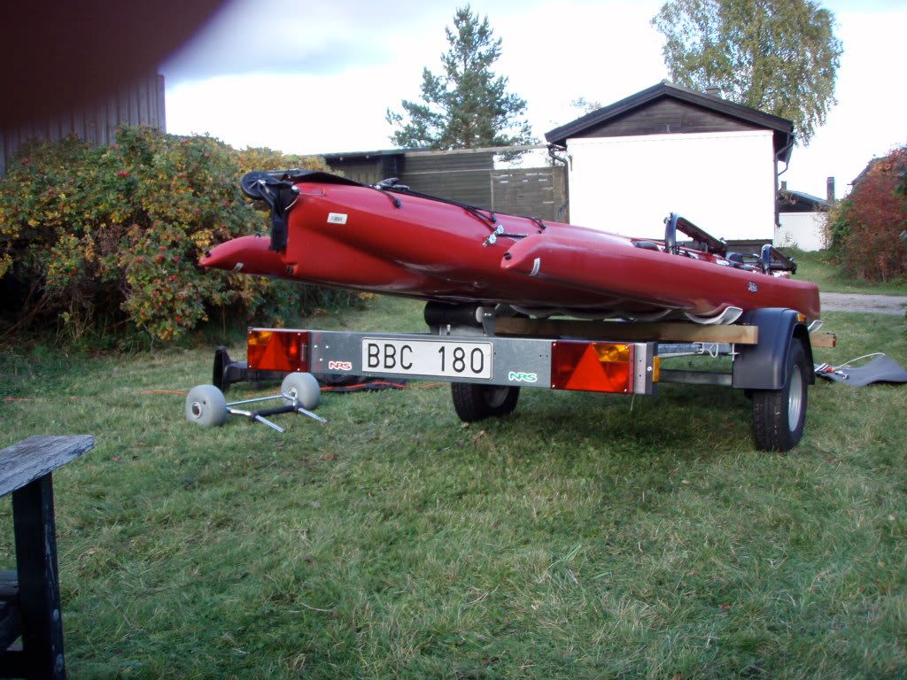
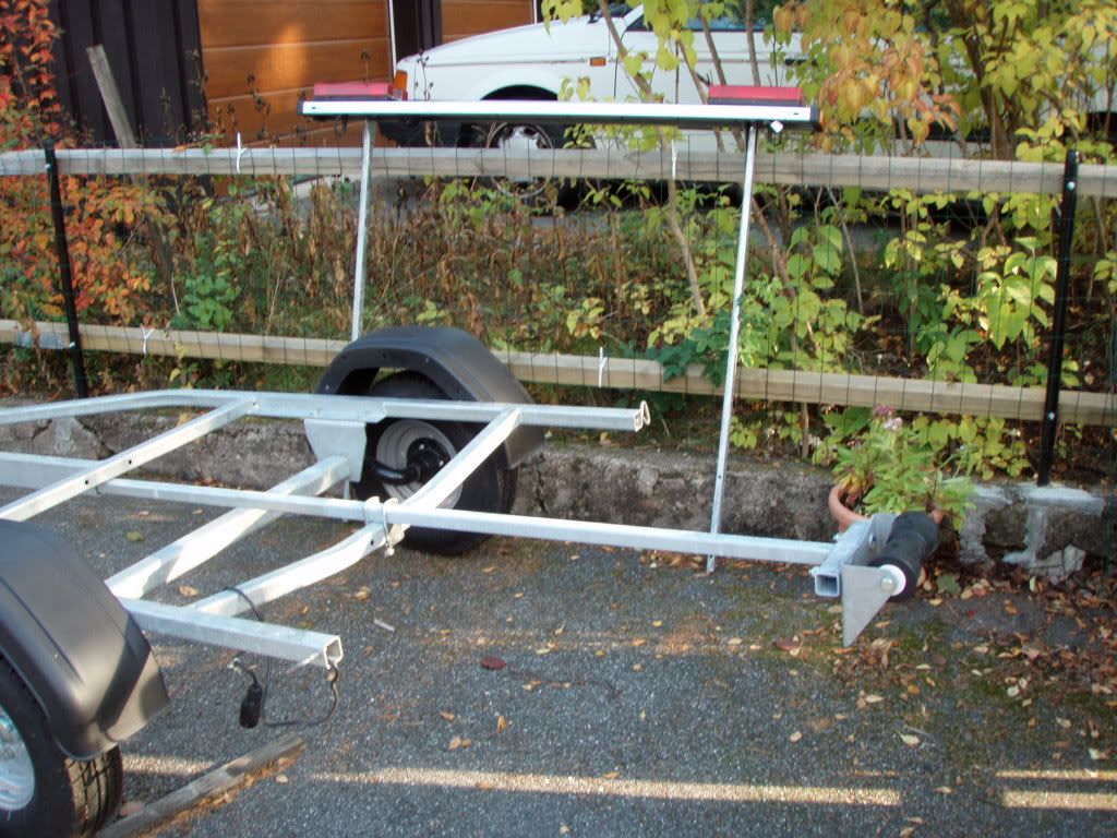
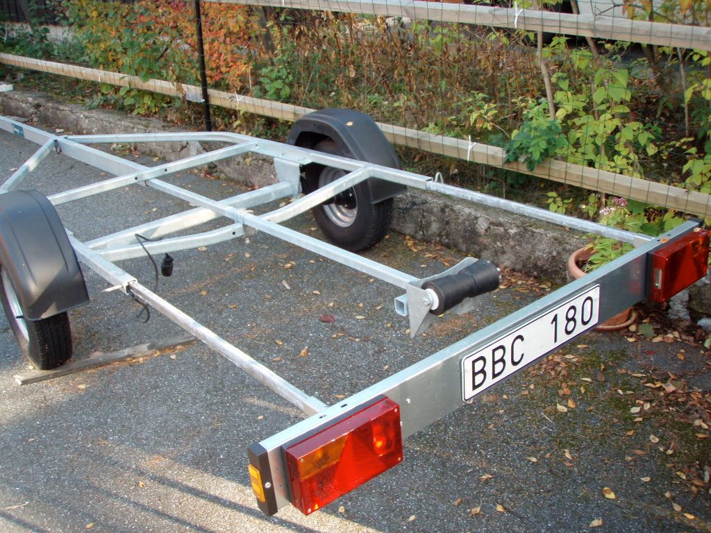
10. Licence plate and light panel was removed to fit the new bar. It is also removed at launching.
11. Licence plate and light panel fitted again.
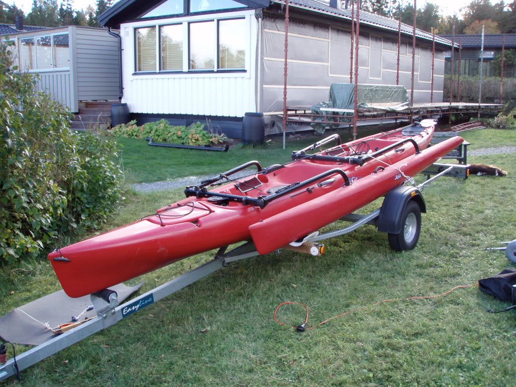
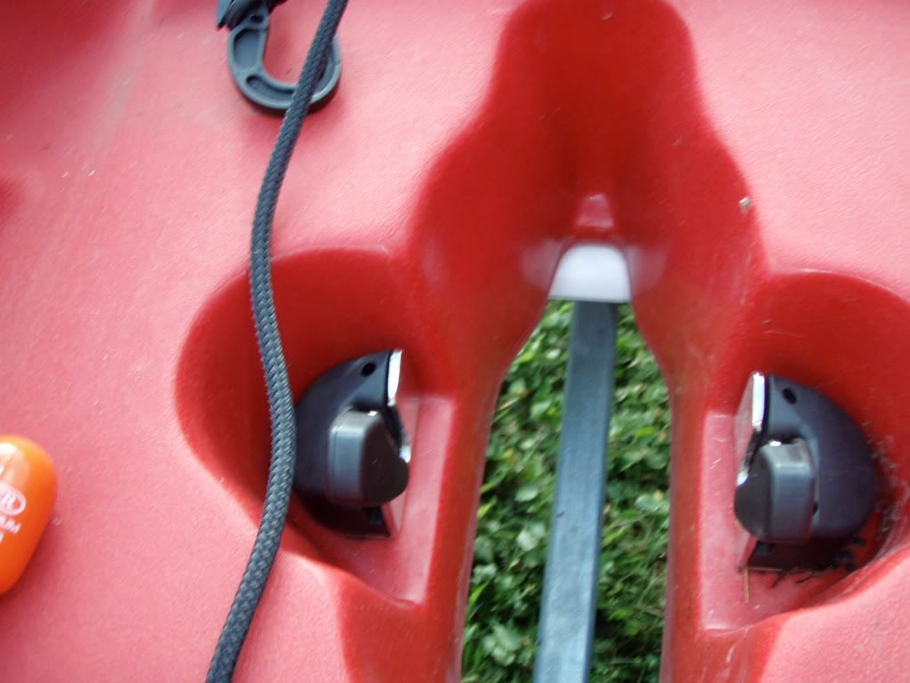
12. The cradles are fitted to the wood beams. I did fit the aft beam just behind the mudguard and the front beam 67” (1700 mm) in front of the aft beam. The measurement is centre to centre.
13. The forward cradle is placed under the forward well.
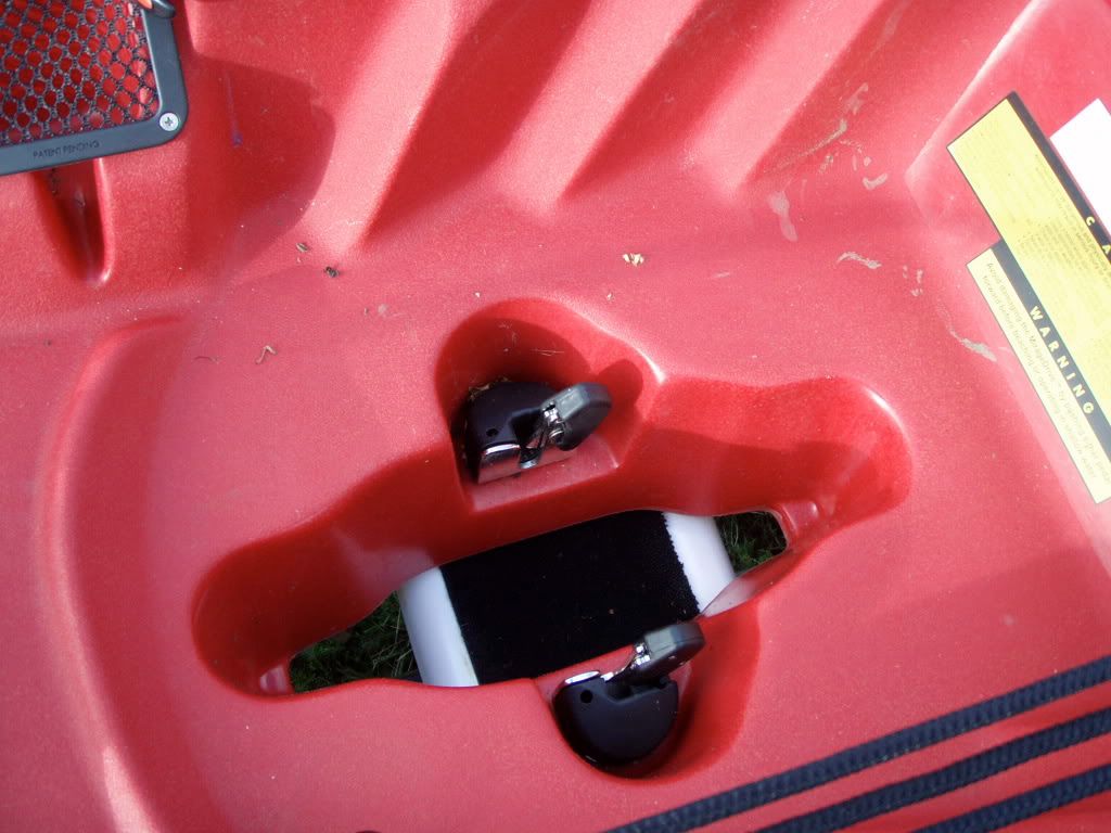
14. The aft cradle is placed just at the aft edge of the aft well.
15. I was lucky that the forvard keel roller fitted without any modifications.
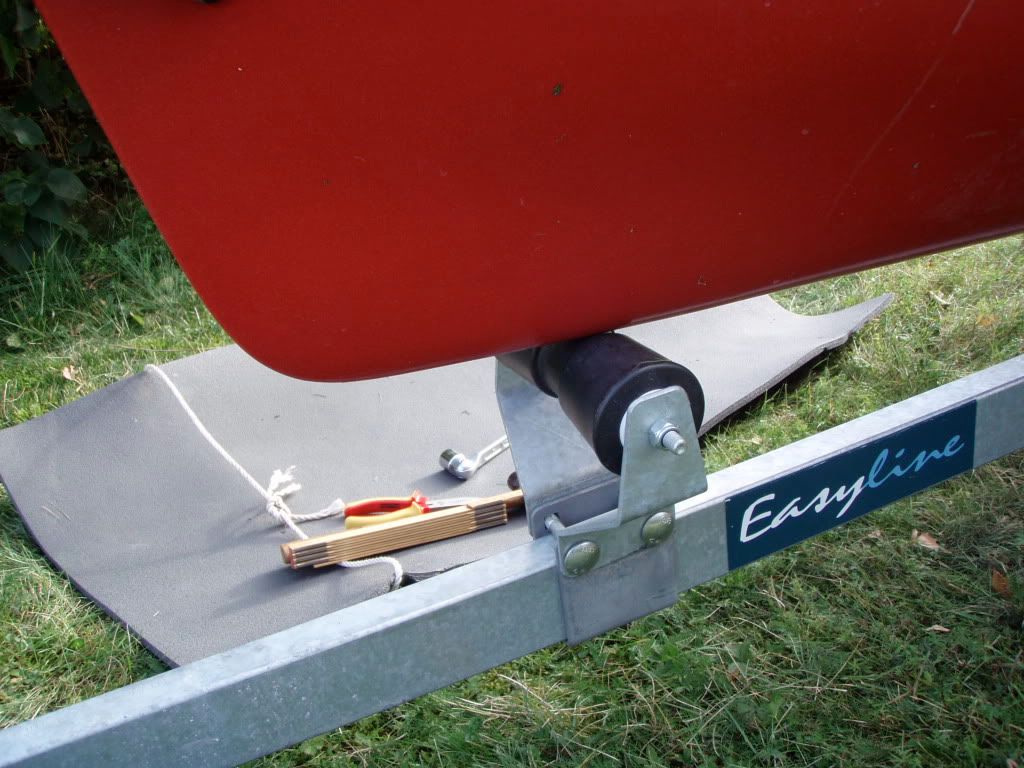
16. I misjudged the height of the aft roller and therefore I will have to make some addition to the new bar.
17. The amas fits just inside the mudgards. The distance between the mudguards is 1170 mm. The width of the TI is actually 1220 mm but the amas are rounded off at the bottom.
18. Loaded and ready to go.